PROTOTYPEWork in progress
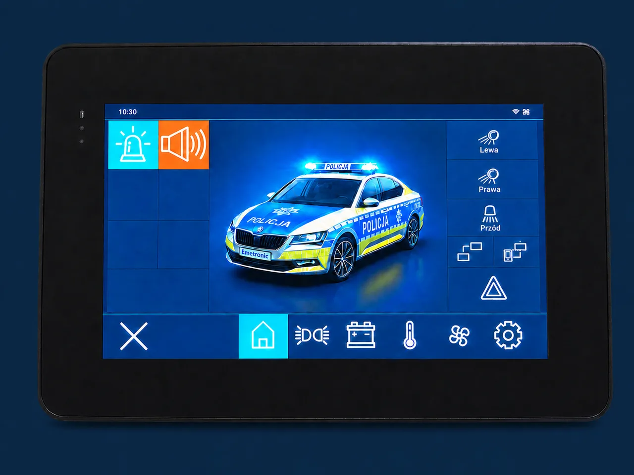
A touch panel controlling the whole vehicle
Signaling, lighting, power and temperature on one screen. Natively synchronised with EMCORE, not a universal off-the-shelf panel.
Read moreKnowledge base · 24 August 2026
Signaling runs while the incident is running — exactly when communications, the CAN bus and the cameras must work flawlessly. An EMC defect does not show up at random; it shows up whenever the stakes are highest.
A light bar works while the incident is running. That is exactly when the radio, the CAN bus, the cameras and the sensors have to work flawlessly. If the signaling interferes with those systems, the failure does not happen “sometimes” — it happens at the worst possible moment every time. Because switching on the lights and the critical moment are, by definition, the same moment.
This article shows where the difference between “meets R10 on paper” and “causes no trouble in the vehicle” comes from — using cases we have seen in service and while diagnosing installations.
Within a few square metres of roof you find:
The distances between them are 30–80 cm. A receiver expected to pick up a signal of a few microvolts works half a metre from a switching device. This is the near field — coupling that no measurement taken several metres away in a laboratory describes.
And the roof is only the beginning. The rest of the build runs on the same electrical system: the fire pump and its controls, motors for masts, winches and platforms, hydraulic pumps, generators and 230 V inverters, parking heaters, chargers for radios and torches, terminals and on-board computers, recorders — and in ambulances the medical equipment: defibrillator, ventilator, suction unit. Some of these are sensitive victims of interference; others — such as the brushed motors in pumps and drives — generate it themselves. All of it is tied together by a shared supply line, harnesses running parallel to video cables and buses, and a ground realised through the mounting points. Every one of those is a path by which interference reaches places it should not.
UN Regulation No. 10 is the legal basis: it tests emission (broadband and narrowband) and the immunity of an electrical sub-assembly under laboratory conditions, in a defined configuration. We cover the regulation itself in a separate article — what interests us here is what the approval test does not check:
A service report: incorrect triggering of an EMCORE ULTRA amplifier in a finished build. The first suspect is — as usual — the amplifier. Diagnosis on the vehicle, oscilloscope on the main supply line. On the voltage waveform you can see… the flash pattern of another manufacturer's lamps working in the same installation. Every flash is a current spike which, without proper input filtering, shows up as voltage ripple across the whole vehicle's electrical system.
The amplifier was perfectly sound — it was reacting to interference that another device was feeding onto the shared supply. The proof was on the oscilloscope screen: disturbances perfectly synchronised with the rhythm of the flashes.
And here is the fundamental point: a properly designed lamp has no business producing such an effect. Input filtering exists so that the device's operating waveform stays inside it — rather than being drawn across the supply bus of the entire vehicle. If the flash pattern is visible on an oscilloscope on the main supply line, the scale of the conducted emission shows that the input filtering is not doing its job — whatever the documentation declares.
This is textbook conducted emission: the interference does not travel through the air but along the wires — and it reaches everything that shares a supply line with the lamp. The victim may be a siren amplifier, a controller, a camera or any other on-board device. Interference does not choose.
Analogue cameras (composite signal) are exceptionally sensitive to interference. The symptoms are familiar from service: bars across the image, “snow”, the signal breaking up in time with the flash pattern and, in extreme cases, the image disappearing entirely with the full signaling on.
Now the context: the driver is reversing a vehicle weighing over ten tonnes at an incident scene, with people and equipment around. That is exactly the moment when the camera image disappears — because the lights are on. The cause is often coupling into a video cable routed in the same harness as the lamp supply, or radiated emission from unshielded modules.
The most dangerous scenario, and the hardest to catch. Broadband interference from the converters raises the noise floor at the antenna — the receiver is desensitised. Strong, nearby stations are still audible. The weak ones disappear: the distant dispatcher, the rescuer with a handheld radio out in the field.
Emissions from switching converters are not an even hiss but a comb of harmonics of the switching frequency. Whether one of those harmonics lands exactly on a user's channel is a matter of the local frequency allocation, not of the device's “general quality”. And allocations differ:
Hence a phenomenon that surprises many: the same type of light bar works faultlessly in one region and generates complaints about communications in the next. Not because the units differ — because the harmonics land on a different channel grid.
On top of that come band migrations. Services are moving from analogue systems to digital ones and between frequency ranges. A product “tuned” to happen to miss one customer's channels will come back as a warranty claim after the first change of communication system. That is why there is no point aiming at individual frequencies — the device has to be clean across the band.
When interference appears, the trade has a standard repertoire: ferrites clamped onto the harness after the fact, shielding tape, the advice to “move the antenna cable away”, switching to a less aggressive flash pattern, an extra filter added by the upfitter. All of that treats symptoms. It does not transfer between vehicles, it is sensitive to every modification of the installation, and it is always one service visit too late.
Emertronic's approach is the opposite: the problem is not to arise in the first place. In practice that means:
It is a difference of philosophy: not “how to pass the test”, but “how not to generate the problem”.
If you are responsible for building up an emergency vehicle, these questions will tell you more about a supplier than any catalog:
A supplier who answers with specifics understands the problem. A supplier who answers “we have R10 approval” has just told you everything.
Type approval is a starting point, not proof of EMC quality. In a vehicle running on lights, electromagnetic compatibility is not a line in a table — it is the condition for the radio, the cameras and the buses working exactly when they are needed most. What R65 categories and classes and the R10 requirements mean exactly is covered in separate articles.
Do you have a vehicle in the fleet showing signs of interference with the signaling on? Get in touch — we diagnose the cause, not the symptoms.
An engineer, not a call center. We answer specifically, with regulation numbers.